For over 11 years I’ve been typing on a self-soldered ErgoDox keyboard with parts bought from MassDrop. A couple of years after building it, I added a TrackPoint harvested from a second-hand ThinkPad keyboard.
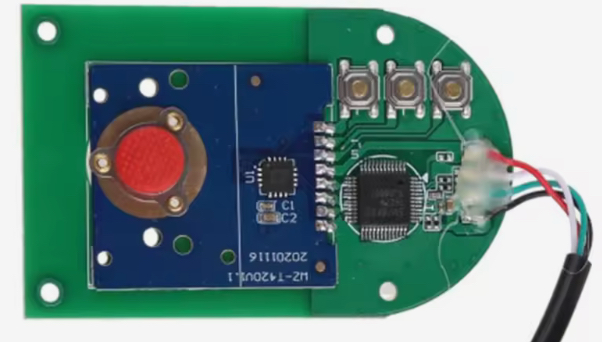
Later I swapped the acrylic case for wood. In the process I broke the TrackPoint board’s fragile legs and needed a replacement. I found a Chinese TrackPoint module. It is sold under different names such as SurnQiee TrackPoint or Rocker Mouse Pointer on Amazon and AliExpress, prices ranging from 13 to 50 EUR, but all looking the same.
The module contains two ICs: a small one beside the red TrackPoint sensor, and a larger one close to the USB cable. The USB-side chip turned out to be an EM85F684A microcontroller. I assumed the sensor-side IC converts the TrackPoint signals to PS/2 for that microcontroller.
I initially dodged the investigation by hiding a tiny USB hub inside the keyboard so both the Teensy and the TrackPoint shared a USB single cable. It worked but was quite flaky. Time to do it right.
I want the cleaner design back: remove the TrackPoint module’s microcontroller and wire the sensor-side IC directly to the Teensy (like my original ThinkPad mod). To do that I first need to confirm the interface is PS/2 and identify clock vs data pins, without buying a logic analyzer. So I built a quick-and-dirty analyzer using the same Teensy 2.0 already in the keyboard.
Verify the SurnQiee sensor-side IC speaks PS/2 to its microcontroller and identify which pin is clock and which is data.
curl, make, gitavr-gcc, teensy_loader_cliOther dependencies are fetched automatically in the deps folder.
Source code: https://github.com/db7/chadilat
  Teensy 2.0                                      Mouse IC
+--------------+                             +----------------+
|          GND +-------------------+---------+ GND            |
|          PB0 +--- 1kΩ -----------|-+-------+ X0             |
|          PB1 +--- 1kΩ -----------|-|-+-----+ X1             |
|          PB2 +--- 1kΩ -----------|-|-|-+---+ X2             |
|              |                   | | | |   |                |
+----[USB]-----+                           --+ VCC            |
                                  Micro    --+ BTN1           |
                               Controller  --+ BTN2           |
                                  [USB]    --+ BTN3           |
                                             +----------------+
If you want to try that as well, wire PORTB to the TrackPoint circuit (use 1 kΩ series resistors), ensure a common ground between with Teensy, and ensure the TrackPoint is also operating at 5V.
Then, flash the Teensy with the analyzer firmware. Connect over USB and run:
reader/reader /dev/ttyU0 | tee output.dat | viewer/viewer
Mask/choose pins in firmware/reader/viewer source. No config files — edit the source.
The firmware samples the 8-bit PINB register in a tight loop and streams records (with timestamps) over USB serial. A hardware timer provides timestamps; a small buffer amortizes USB I/O. The desktop viewer (Raylib) plots transitions so PS/2’s clock/data are easy to spot.
This is sufficient because PS/2 is ~10–16 kHz and the Teensy 2.0 at 16 MHz can sample it comfortably. It’s not a real logic analyzer, but it’s good enough for low-speed protocols like PS/2.
Each PS/2 frame is 11 bits: start(0), 8 data bits LSB-first, odd parity, stop(1). And that matches quite well the output I got. Here is a screenshot:

These clean frames confirm the interface is PS/2 and that data=PB0 and
clock=PB1. PB2 seems to be connected to the reset pin.
In conclusion, I think these TrackPoint modules are a good alternative, cheaper and nicer than buying a second-hand ThinkPad keyboard just to destroy it to extract the TrackPoint.
With clock and data identified, the plan is to separate the sensor-side IC from its on-board microcontroller and wire the IC directly to the Teensy 2.0 (PS/2 data/clock + power/ground). That removes the flaky USB hub workaround and returns to a single, reliable USB device (ie, the Teensy) exposing both keyboard and TrackPoint functionality.
© 2025 db7 — licensed under CC BY 4.0.